Cross Country Wireless introduces an HF Upconverter

Cross Country Wireless introduces an HF Upconverter
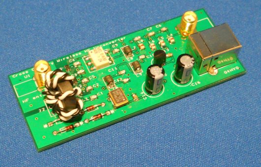
The CCW HF Upconverter (Photo: Cross Country Wireless)
(Source: Southgate ARC)
Cross Country Wireless have just released a HF Upconverter. This will allow HF or VHF SDR receivers such as the RTLSDR dongles, Funcube or our own SDR-4+ receiver to work on HF, LF and VLF.
Unlike other upconverters currently available we have added the RF protection features from our SDR-4+ receiver including an antenna isolation transformer and RF over-power protection. This protects the SDR receiver or dongle and the attached PC from damage caused by static electricity charges on the antenna or nearby high power transmitters.
There are two versions of the Upconverter. One has a 125 MHz local oscillator and the frequency range is 12 kHz to 45 MHz. This is intended for use with the RTLSDR and Funcube dongles.
The other version has a 10 MHz local oscillator and is designed for use with the SDR-4+. This has a frequency range of 12 kHz to 1.6 MHz.
Here are some of the specifications Cross Country Wireless  has published for the HF Upconverter:
Technical data – 125 MHz version for RTLSDR and Funcube dongles
  • Frequency range: 12 kHz to 45 MHz
  • Input impedance: 50 ohms
  • IF rejection: > 60 dB
  • Local oscillator frequency: 125 MHz
  • Local oscillator level at antenna socket: < -50 dBm
  • Gain: -6 dB
  • RF connectors: SMA female
  • Power connector: USB B
Technical data – 10 MHz version for SDR-4+ receiver
  • Frequency range: 12 kHz to 1.6 MHz
  • Input impedance: 50 ohms
  • IF rejection: >100 dB
  • Local oscillator frequency: 10 MHz
  • Local oscillator level at antenna socket: < -60 dBm
  • >Gain: -6 dB
  • RF connectors: SMA female
  • Power connector: USB B
Also, from CCW on YouTube:
“This is a video of a Cross Country Wireless HF Upconverter used with a CCW SDR-4+ receiver to listen to VLF and LF transmissions using a half wave dipole cut for the 80m amateur band.”
There are 20 second samples of the following stations:
  • BBC Radio 5 Live on 693 kHz AM
  • BBC Radio 4 on 198 kHz AM
  • GYN2 Skelton on 81 kHz FSK
  • MSF Anthorn on 60 kHz time signal
  • GQD Anthorn on 22.1 kHz Anthorn
  • GQD Anthorn on 19.6 kHz
This version of the Upcoverter uses a 10 MHz local oscillator so the frequency displayed is 10 MHz higher than that received i.e. 10.693 MHz = 0.693 MHz = 693 kHz.

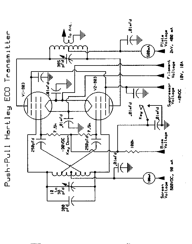
A Push-Pull Hartley VFO transmitter .

A Push-Pull Hartley VFO transmitter . 


This is a variation of the the Electron Coupled Oscillator circuit, pioneered by Dow in 1931. Dow's ECO has the screen "grounded" for RF. In this circuit, because I am using filament-type tubes instead of heater-cathode types, and because I didn't want to build or use a pair of filament chokes with this first attempt, I chose to use the "cathodes" as the "grounded" or "common" electrode. I am hoping that it otherwise works much the same way as the standard ECO: i.e., the cathode-grid-screen are the oscillator section, with the screen acting as the oscillator's plate, and the plate of the tube and its associated tuned circuit making up the amplifier section of the transmitter. So, essentially, we have two tubes performing the work of four. Should be interesting. This circuit uses grid-block keying, and all components, with the exception of the values of tuned circuit components, are shown on the schematic. Plate voltage should be about 1500 VDC, screen voltage should be 300 - 500 VDC, suppressor voltage should be about 40 VDC, and bias (actually blocking bias) should be about -150 VDC. Power input should not exceed about 150 watts. Adjust voltages and loading for best keying. It might be better to use a push-pull grid/parallel plate (push-push) circuit, as suggested by one of the members of the GB list. The plate circuit would then be tuned to twice the grid circuit frequency. This should provide much better stability, and eliminate any parasitics or need for neutralization. Experimentation is in order.
For any of these oscillator circuits which use tetrodes or pentodes, be sure to never apply screen voltage before applying plate voltage. Otherwise the screens may disappear in a blinding flash of light. This circuit should feed a good antenna coupler.


"High-Power" Push-Pull Crystal Oscillator

"High-Power" Push-Pull Crystal Oscillator 

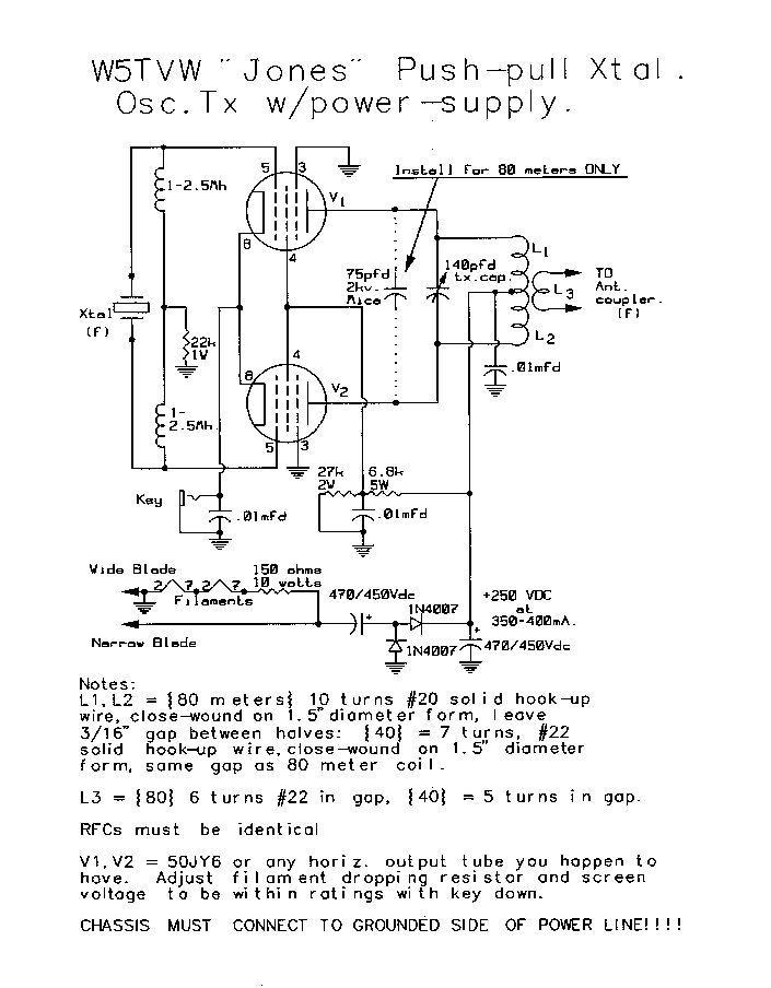
Designed by "Sandy" Blaize, W5TVW, and first published in the BA-dedicated magazine, "Electric Radio". It is an adaptation of the Frank Jones original, which we have also shown on these pages. This transmitter may be used on 160, 80, and 40 meters, and would probably work just fine on the other Amateur Bands as well, although it has not yet been tried there. The power supply could be changed to a voltage-tripler, or quadrupler easily enough. The rig provides 90 watts or so input as drawn with the 1/2 wave voltage doubler, but could run as much as 150 watts input if the HV was higher. Sandy mentions that the screen voltage, and to a lesser extent, the filament voltage MUST be set to the correct value KEY DOWN.
The power oscillator was a tuned push-pull oscillator with no further amplification, pictured belowThe German V2 jammer

Low-power-inverter

Low-power-inverter

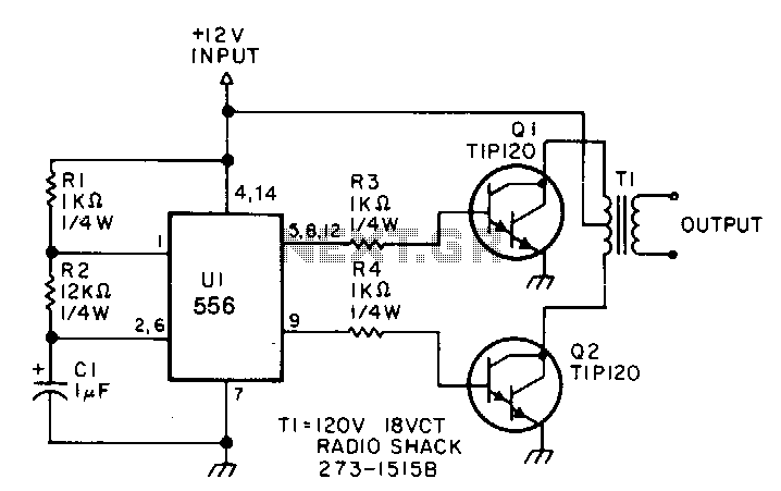
This low-power inverter uses only 9 parts and turns 10 to 16 Vdc into 60-Hz, 115-V square-wave power to operate ac equipment up to 25 W. The first section of the 556 timer chip is wired as an astable oscillator with R2 and C1 setting the frequency. The output is available at pin 5. The second section is wired as a phase inverter. That output is available at pin 9. Resistors R3 and R4 keep output transistors Q1 and Q2 from loading down the oscillator.


The two transistors drive the transformer push-pull fashion. When one transistor is biased-on, the other is cut-off. The transformer is a 120 V/18 VCT unit that is connected backwards, so that it steps the voltage up rather than down. Oscillator circuit U1, R1, R2, and C1 operates from about 4 to 16 V with a very ~stable output. 

Dipolo

.
Éste dipolo para banda de 40 y 80 Mts. con bobinas, es un excelente proyecto -archi probado- en banda de 40 Mts. tiene el mismo comportamiento de un dipolo de 1/2 onda normal , y en banda de 80 Mts. baja un poco su rendimiento por las bobinas naturalmente, el punto a favor es su reducido tamaño. Es la antena que más hemos construido, como estas 2 bandas son las que más utilizamos, y  con la incorporación de la bobina da la posibilidad a muchos colegas que no tienen espacio físico para colocar un dipolo de 1/2 onda para banda de 80 mts. es una real solución, en el esquema superior están los detalles para la construcción, vale la pena tenerla aunque sea para llevarla en viaje de fin de semana, o de vacaciones.
.
Materiales:
  • 2 Bobinas  PVC de 40mm de diámetro -14 cms. largo c/u.
  • 65 vueltas de alambre de Cu de 1 mm de espesor  esmaltado.
  • 4 tapas ciegas de PVC de 40 mm.
  • 4 ganchos con doble tuerca 1/4¨ zincado.
  • 8 remaches pop.
  • 8 terminales de bronce para soldar.

Antenas

ANTENNA-MOVIL-152040MTS
He fabricado una antena móvil para un apreciado amigo, tiene 3,06 Mts. de largo – 1,25 Mts. el barral, la bobina 11,4 cms. y el látigo superior de 1,70 Mts.- en una sola bobina 3 bandas, 10-15 y 20 Mts. La bobina de plástico industrial de 1 3/4 (45 mm) de diámetro por 4 1/4 (10,7cms.) de largo, son 10 vueltas de alambre de cu. esmaltado de 1 mm. de espesor, para la banda de 20 Mts. y luego 27 vueltas de alambre de cu. esmaltado para la completar la bobina de 40 Mts. para acoplarla la bobina para banda de 15 se debe colocar cable que sirve de conección en el pernito superior, y ya la tendremos resonando en los 21 KHz. si conecto al medio en 14 KHz. y sin conección para 7,0 KHz.  Había descontinuado la fabricación de éste tipo de bobinas multibanda, porque se requiere de bastante paciencia y tiempo, para llevar a feliz término el trabajo, pero la amistad pudo mas. Testeado final , en banda de 15, 20 y 40 Mts. 20 Mts. mínima reflejada/estacionaria 1:1. Estábamos en amable plática en 20 Mts. con el amigo Alberto LU1GBO con su fiel Atlas 210 X y la tribanda Palombo, me reportó un 59+ 20, seguidamente apareció José EA8ES de Tenerife Canarias con un 59+10 -no podía creer que estuviera móvil – y luego le sucedieron Juancito LU4VL, Marcelo LU7DEB con la antena JVP apuntando para acá 59+20. Yo estaba con el Kenwood TRC-80 con 200 vatios, a esperar que llegue mi amigo para instalarle en la pick-up Mazda. Me olvidaba, en las fotos está aún sin terminar, falta regulación final en el móvil definitivo y luego le pongo la funda termo-contraíble.